Shearwater lies in the Central Graben area of the central North Sea, approximately 200km east of Aberdeen in 90m (995ft) of water. Owing to the nature of the reservoir, it was necessary to complete the drilling of all development wells before production started.
The five high-pressure / high-temperature (HP / HT) development wells were drilled using the jack-up Maersk Endurer at a cost of over £25 million each.
The HP / HT wells are over three miles long and subjected to the additional presence of hydrogen sulphide, carbon dioxide and concentrated salt solution. The downhole architecture features a variety of materials necessary to survive the conditions.
Each well contains over 1,000t of heavy wall, high-tensile steel and chrome tubes.
Wellhead platform details
The wellhead platform topsides design contract was fabricated at Heerema Hartlepool. Each well flowline is combined into a common production manifold and piped across the bridge, to the primary separator on the processing platform. The reservoir fluids are produced at the relatively high temperatures of 248-284°.
Shearwater is produced using a central processing facility (CPF), which is bridge-linked to a wellhead platform (WHP) 80m away.
The topsides are supported by a 5,900t steel jacket, which is designed to withstand 100-year wave heights of 23.8m and accidental events such as an impact from a 5,000t vessel, or a jet fire from the riser. The lift-installed 115.5m-high assembly supports the integrated deck at four load-bearing points.
The jacket is fixed by eight 2.75m-diameter piles, two for each leg, penetrating 43m into the seabed. The structure spans 35m x 24m at the deck stab-in points and 48m x 38m at the seabed.
AMEC built the process, utilities and quarters (PUQ) facilities at Wallsend. Heerema’s Hartlepool yard handled the wellhead topsides bridge, flare, main jacket and piles. The main platform topsides facilities comprised a 15,000t (final operating weight) integrated deck, including a compression module, a flare tower and an accommodation module for 78 people.
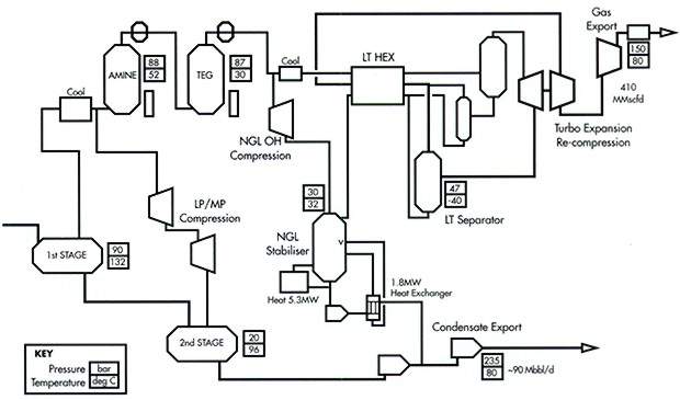
The wellstream is separated into gas and condensate on the CPF. Plans envisage that high pressure will be reduced through chokes, prior to two-stage three-phase separation, with the primary separator operating at 90bar. The first stage separates gas, liquid hydrocarbon (condensate) and water.
Gas sweetening (H2S and CO2 removal) is carried out by an amine plant, while the regeneration tail gas will be disposed of using incineration. About two tonnes of hydrogen sulphide gas is disposed of each day via the incinerator unit, which turns it into sulphur dioxide.
This is mixed with seawater to create sulphate ions, which occur naturally in seawater and can be safely returned there without environmental risk.
Installation
To install the platform, six barges transported the jacket, piles, wellhead deck, cabins module, integrated deck, flare, bridge and incinerator package on a 180-mile journey from yards to the site. The world’s second-biggest lifting vessel, the Thiaff, carried out the installation in two phases, over ten days.
Export: condensate and gas
Separated condensate is transported ashore via a 24in-diameter, 8km (five-mile) spur pipeline, to connect with Elgin / Franklin fluids export. The liquids are then transported 37km via another 24in pipeline to the Marnock Wye.
It then travels to Cruden Bay via the BP Unity Platform in the Forties Pipeline System (FPS). The new 34in-diameter, 463km (290-mile) SEAL gas pipeline connects to the Shell / Esso gas-reception terminal at Bacton.


